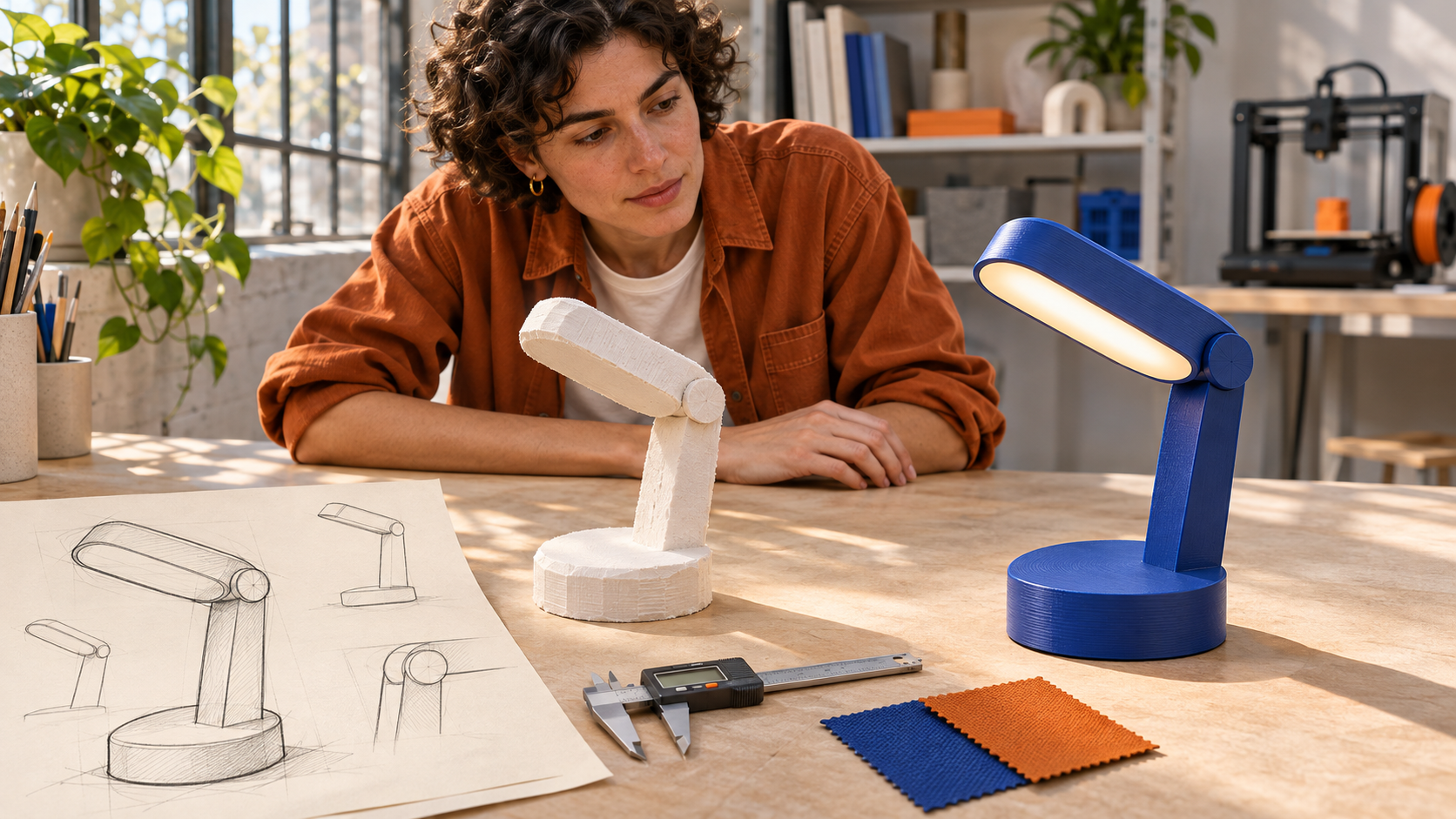
The Digital-to-Physical Renaissance in Hardware Engineering
\n
For more than a century following the dawn of modern industrial mass production, the transition from a mechanical engineering drawing to a physical prototype was an agonizing, slow, and exorbitantly expensive endeavor. Highly skilled patternmakers, machinists, and toolmakers spent weeks—often months—manually carving wood patterns, grinding sand-casting molds, and milling prototype steel fixtures on manual Bridgeport knee mills. If a designer altered the curvature of a grip or shifted a mounting boss by three millimeters, the entire manual machining cycle had to be restarted from scratch. Consequently, engineering iterations were kept to an absolute minimum, stifling creative exploration and forcing companies to commit to unproven designs before physical validation.
The dawn of Additive Manufacturing (AM) and Rapid Prototyping (RP) has permanently shattered this technological paradigm. By decomposing three-dimensional computer-aided design (CAD) solid models into discrete, micron-thin mathematical slices and physically depositing matter layer upon layer, additive manufacturing decouples geometric complexity from tooling overhead. As the legendary manufacturing adage proclaims: In additive manufacturing, complexity is free.
Today, rapid prototyping is no longer merely a technique for producing fragile visual show-and-tell models; it is a mission-critical industrial discipline encompassing high-performance photopolymers, engineering-grade sintered thermoplastics, and direct metal laser melting capable of producing fully functional end-use production hardware. In this comprehensive technical treatise, we explore the physics, photochemistry, material science, and mechanical testing protocols of the dominant additive manufacturing technologies driving modern product development.
\n
🔬 The Shift: From Rapid Prototyping to Additive Manufacturing
‘Rapid prototyping was historically about building sacrificial geometric models to verify spatial fit. Modern Additive Manufacturing is about engineering isotropic, load-bearing mechanical components with certified tensile strength, thermal resistance, and chemical durability suitable for end-use aerospace, medical, and consumer products.’
\n
Stereolithography (SLA): Photopolymerization and Micron-Level Precision
\n
Patented in 1986 by Chuck Hull, the co-founder of 3D Systems, Stereolithography (SLA) represents the historical foundation and the cosmetic benchmark of additive manufacturing. SLA operates on the photochemical process of vat photopolymerization, wherein a liquid, light-sensitive monomeric resin is selectively exposed to a concentrated beam of ultraviolet (UV) laser light (typically operating at a wavelength of 355 nm or 405 nm), inducing radical polymerization that cross-links the liquid into a solid, thermoset polymer matrix.
In a standard inverted desktop SLA system (or large-scale industrial top-down vat system):
- Galvanometer Scanning: High-speed optical scanning galvanometers direct the UV laser spot across the bottom of a transparent resin vat, tracing the exact cross-sectional slice geometry with XY positioning accuracies exceeding 25 microns (0.001 inches).
- Photocuring Kinetics: The laser energy initiates an instant photochemical cascade, transforming low-viscosity liquid acrylate or epoxy oligomers into densely cross-linked solid networks within milliseconds.
- Z-Axis Elevation: The build platform ascends by layer increments ranging from 25 to 100 microns, fresh liquid resin flows beneath the cured slice via automated wiper blades or passive peeling mechanisms, and the subsequent slice is photocured onto the preceding layer.
The undeniable engineering advantage of SLA is its extraordinary dimensional accuracy, isotropic mechanical behavior in comparison to extrusion methods, and peerless surface finish. SLA parts display virtually zero visible layer stair-stepping, making SLA the undisputed technology of choice for cosmetic appearance models, lens prototyping using optically clear resins, micro-fluidic channels, and investment casting sacrificial patterns.
\n
| Additive Technology | Fundamental Physics / Mechanism | Compatible Engineering Materials | Layer Resolution (Z) | Primary Prototype Application |
|---|---|---|---|---|
| Stereolithography (SLA) | Vat photopolymerization via UV laser | Liquid epoxy/acrylate photopolymers, ceramic resins | 25 – 100 microns | High-precision cosmetic models, optical lenses, master casting patterns |
| Fused Deposition Modeling (FDM) | Material extrusion of molten thermoplastic filament | ABS, Polycarbonate (PC), PLA, PEEK, Ultem 9085 | 100 – 300 microns | Durable functional test brackets, rugged jigs, thermal air ducts |
| Selective Laser Sintering (SLS) | Powder bed thermal fusion via CO2/fiber laser | Polyamide (Nylon 11, Nylon 12), TPU, Glass-filled PA | 60 – 120 microns | Complex functional assemblies, snap-fits, living hinges, batch production |
| Direct Metal Laser Sintering (DMLS) | Powder bed laser melting of metallurgical micro-powders | Ti-6Al-4V titanium, Inconel 718, 316L Stainless, AlSi10Mg | 20 – 60 microns | Mission-critical aerospace brackets, conformal cooling injection mold inserts |
| PolyJet / MultiJet Printing | Piezoelectric jetting of liquid photopolymer droplets | Multi-durometer elastomeric & rigid hybrid resins | 14 – 30 microns | Over-molded soft-grip handles, multi-color packaging prototypes |
\n
Fused Deposition Modeling (FDM): Thermoplastic Extrusion and Mechanical Ruggedness
\n
Invented by S. Scott Crump in 1988 and commercialized by Stratasys, Fused Deposition Modeling (FDM)—broadly classified under ISO/ASTM 52900 as Material Extrusion—is the most widely deployed additive technology on the planet. Rather than curing liquid resins, FDM feeds a continuous spool of solid thermoplastic filament (typically 1.75 mm or 2.85 mm in diameter) into a temperature-controlled heating block known as the hotend.
Inside the hotend, the solid filament is liquified to a semi-viscous state and forced through a precision brass or hardened steel extrusion nozzle (ranging from 0.25 mm to 0.8 mm orifice diameter) under mechanical pressure from drive gears. The printhead traces the toolpath generated by slicing software, depositing molten beads of polymer onto a heated build plate where the material cools, solidifies, and thermally fuses to adjacent and underlying rasters.
The definitive strength of FDM is its direct compatibility with true, standard production-grade thermoplastics. Unlike SLA photopolymers, which are thermoset resins prone to UV yellowing and moisture embrittlement over time, FDM utilizes identical molecular chemistry found in mass-production injection molding: Acrylonitrile Butadiene Styrene (ABS), Polycarbonate (PC), Polyethylene Terephthalate Glycol (PETG), and even aerospace-certified high-temperature polyetherimides such as Ultem 9085 and PEEK.
\n
Anisotropy and the Z-Axis Adhesion Challenge in FDM
\n
However, FDM presents an intrinsic engineering limitation that mechanical engineers must strictly account for during functional prototyping: Mechanical Anisotropy. Because FDM parts are built from stacked horizontal rasters, the intermolecular polymer chain entanglement across the vertical Z-axis layer interface is significantly weaker than the continuous tensile strength along the XY extrusion paths. Under heavy tensile or bending stress, FDM parts consistently fail along layer boundary planes (delamination).
To overcome this, engineers utilize heated build chambers (operating at temperatures exceeding 120°C in industrial Stratasys machines) to maintain the part near the polymer’s glass transition temperature ($T_g$), promoting deeper thermal fusion and molecular re-entanglement across layer interfaces. Furthermore, mechanical engineers strategically orient functional prototypes on the virtual build plate so that maximum tensile and shear stress vectors align parallel to the XY build plane rather than perpendicular across the Z-axis.
\n
📐 Orientation Dictates Strength
In FDM 3D printing, a cantilevered mounting bracket loaded vertically will fail at 40% of its rated tensile yield strength if printed standing upright along the Z-axis due to inter-layer cleavage. Printing the exact same CAD model resting flat on its side aligns the continuous polymer extrusions with the load path, maximizing mechanical strength.
\n
Selective Laser Sintering (SLS): Powder Bed Fusion and Support-Free Freedom
\n
For complex mechanical assemblies, kinematic linkages, and living hinges, Selective Laser Sintering (SLS) stands as the pinnacle of polymer additive manufacturing. Developed at the University of Texas at Austin by Dr. Carl Deckard, SLS is a Powder Bed Fusion (PBF) technology that completely eliminates the need for sacrificial support structures.
The SLS process begins with a heated powder delivery chamber filled with micronized spherical polymer powder—most commonly Polyamide 12 (Nylon 12) or Polyamide 11 (Nylon 11). A precision counter-rotating roller spreads an ultra-uniform layer of powder (typically 100 microns thick) across the build bed. The entire build chamber is preheated to just a few fractions of a degree below the polymer’s melting point. A high-power infrared CO2 or fiber laser traces the cross-section, providing the minute thermal energy delta required to sinter and fuse the powder particles together without causing liquid splashing.
Because every cured cross-section remains fully enveloped and supported by the surrounding bed of unfused loose powder, SLS can fabricate geometrical features that are physically impossible to produce with SLA, FDM, or even 5-axis CNC machining: internal hollow channels, complex lattice shock-absorbers, and pre-assembled interlocking mechanical chains and universal joints that emerge from the machine fully functional and ready to operate once loose powder is blasted away with compressed air.
\n
Direct Metal Laser Sintering (DMLS): Additive Metallurgy in Critical Engineering
\n
When prototype applications demand extreme structural stiffness, cryogenic survivability, or operating temperatures exceeding 800°C, polymer prototypes yield to Direct Metal Laser Sintering (DMLS) and Selective Laser Melting (SLM). Operating within sealed, argon-purged inert gas atmospheres to prevent explosive oxidation, DMLS directs multi-kilowatt ytterbium fiber lasers into micro-beds of atomized metal powders.
DMLS is capable of fully melting engineering alloys including aerospace-grade Titanium (Ti-6Al-4V Grade 5), high-temperature nickel superalloys (Inconel 718 and Inconel 625), surgical-grade Stainless Steel (316L), and structural Aluminum (AlSi10Mg). Parts achieve 99.8% metallurgical density, matching or exceeding the fatigue and tensile properties of conventional wrought or cast alloys.
In product development and tooling engineering, DMLS has revolutionized injection mold design through the implementation of Conformal Cooling Channels. Traditional CNC toolmaking can only drill straight, linear water cooling lines into hardened steel molds. With DMLS, engineers can print injection mold cavity inserts with organic, curved internal cooling passages that hug the exact three-dimensional contours of the plastic part. This eliminates localized thermal hotspots, reduces plastic injection molding cycle times by 30% to 50%, and permanently prevents part warpage caused by uneven thermal shrinkage.
\n
PolyJet Technology: Multi-Material Digital Photopolymers and Overmolding
\n
When prototyping consumer products featuring multi-material construction—such as a rigid power tool enclosure featuring soft rubberized elastomer overmolding, or medical surgical handles with integrated textured grips—neither standard SLA nor single-nozzle FDM can replicate the production artifact in a single build. This is where PolyJet Technology, developed by Objet Geometries and refined by Stratasys, reigns supreme.
PolyJet operates on an architectural principle analogous to a high-resolution 2D inkjet document printer. The print carriage features hundreds of piezoelectric micro-nozzles that jet microscopic droplets of liquid photopolymer (with droplet volumes measured in picoliters) onto the build tray in layers as thin as 14 to 27 microns. Mounted immediately beside the jetting printhead is an intense UV curing lamp that flashes continuously, solidifying the jetted droplets instantly upon contact.
Crucially, industrial PolyJet machines utilize multi-material jetting heads loaded with multiple distinct resin cartridges simultaneously: blending rigid, opaque photopolymers (such as VeroWhite) with flexible, rubber-like elastomeric photopolymers (such as Agilus30). By jetting precise volumetric ratios of rigid and elastomeric droplets at the microscopic voxel level, PolyJet can produce Digital Materials with predetermined Shore A hardness ratings ranging smoothly from Shore 30A (soft silicone feel) to Shore 95A (hard rubber) to Shore 85D (rigid ABS-like plastic). Industrial designers can evaluate the tactile ergonomics, durometer friction, and mechanical comfort of overmolded power tools and medical instruments weeks before investing hundreds of thousands of dollars in complex multi-shot steel injection tooling.
\n
Post-Processing Science: Chemical Vapor Smoothing, Tumbling, and Plating
\n
A 3D-printed part straight off the build plate is rarely ready for functional validation; it requires structured physical and chemical post-processing to attain engineering-grade mechanical and cosmetic characteristics:
- Chemical Vapor Smoothing: In FDM and SLS parts, microscopic layer lines and surface porosity act as severe stress concentrators and harbor microbial bacteria. In automated vapor smoothing chambers, parts are exposed to a temperature-controlled vaporized solvent (such as ethyl acetate or acetone for ABS/ASA, or specialized eco-solvents for Nylon). The chemical vapor briefly liquefies the outermost 20 to 50 microns of the polymer skin, allowing surface tension to pull the molten resin into a mirror-smooth, sealed gloss finish. This process increases tensile yield elongation, seals against liquid ingress, and produces injection-molded cosmetic quality.
- Centrifugal Vibratory Tumbling: Sintered metal and SLS nylon parts are loaded into high-speed vibratory bowls containing ceramic, walnut shell, or stainless steel media lubricated with chemical compounds. Continuous cyclic abrasion shears away microscopic surface roughness, reducing surface Ra values from 10 microns to under 1.5 microns within hours.
- Electroless Nickel Plating: High-performance SLA and SLS prototypes can be chemically pre-treated and immersed in electroless nickel baths, depositing a uniform 10-to-25-micron metallic nickel coating across every internal and external surface. This metallic cladding increases structural flexural stiffness by up to 300%, provides true electromagnetic interference (EMI/RFI) shielding for internal electronics, and confers exceptional surface abrasion resistance.
\n
Functional Prototyping Protocols: From Aesthetic Form to Destructive Testing
\n
The true value of additive manufacturing during hardware development lies in structured, progressive testing protocols. Experienced hardware teams categorize functional prototypes into three rigorous tiers:
- Looks-Like Prototypes (Cosmetic Validation): High-resolution SLA or PolyJet models finished with automotive primer, sanding, and customized wet-paint spray coatings matching exact Pantone or RAL color swatches. Used to evaluate aesthetic balance, consumer focus group ergonomics, and retail packaging shelf appeal.
- Works-Like Prototypes (Functional Architecture Validation): Skeletal FDM or CNC polycarbonate chassis loaded with prototype PCBs, battery cells, off-the-shelf actuators, and ribbon cables. Used to validate mechanical gear ratios, motor torque delivery, thermal airflow aerodynamics, and electrical sensor calibration without regard for cosmetic exterior appearance.
- Looks-Like-Works-Like Prototypes (Pre-Tooling Validation): High-performance SLS Nylon or DMLS assemblies combining fully functional electronics within production-intent enclosures. These prototypes are subjected to destructive stress testing: torque testing screw boss retention, cycling cantilever snap-fits 1,000 times, and dropping assemblies from one-meter drop test fixtures to verify impact absorption before cutting multi-ton production steel molds.
\n
Conclusion: The Iterative Superpower of Modern Engineering
\n
Additive manufacturing has fundamentally democratized and accelerated the physical invention process. What once required nine months of specialized machining and quarter-million-dollar tooling capital can now be designed in CAD on Monday morning, printed in high-performance polymers or titanium overnight, and subjected to physical wind tunnel or dynamometer stress testing on Tuesday afternoon.
Yet the true mastery of rapid prototyping is not the blind adoption of 3D printing for every component; it is the strategic wisdom to select the precise technology—matching SLA for cosmetic optical clarity, FDM for rugged thermal resilience, SLS for complex kinematic freedom, and DMLS for extreme metallurgical loads. By integrating additive manufacturing deeply into the product development lifecycle, hardware engineering teams compress development cycles, eliminate catastrophic tooling risks, and engineer products that redefine the boundaries of physical possibility.